Large-scale water supply hose lining - Oristano
For years, the domestic water supply network has been affected by problems caused by the poor state of repair and maintenance of the existing hydraulic infrastructure.
In particular, the age and conditions of the large pipelines – works of fundamental strategic importance – and their orography have probably been responsible for disruptions in the supply of water over time. Such situations are often aggravated by problems of a technical and economic nature which may arise when the utility companies are obliged to cope with asbestos cement pipes. According to estimates, the network of asbestos cement pipes amounts to some 125,000 km in Italy.
Asbestos cement pipes, in diameters usually between 150 mm and 500 mm, have been used for making water supply networks since 1916. Their use continued uninterruptedly from the ‘50’s to the ‘80’s owing to their ‘optimum’ properties: nothing was yet known of the danger of asbestos fibre.
Use of ‘trenchless technologies’ has often been discussed in this context as a way of overcoming individual problems relating to large-scale water supply network rehabilitation projects (networks that cross thoroughfares, for example).
Extensive use of trenchless technologies during the execution of a large-scale water supply rehabilitation project has never been called into question.
The principal, Abbanoa SpA, sole integrated water supply service utility for the Sardinia region, decided to take advantage of this opportunity by using trenchless techniques to rehabilitate 6 km of DN500 asbestos cement water supply pipeline situated in the Bosa (OR) locality.
Watch the video
Oristano, Bosa aqueduct
The stretch of pipeline between Barasumene and Monte Contra is the part that supplies Bosa and Bosa Marina, the seaside towns of Porto Alabe, Santa Maria del Mare, Sa Lumenera and the Turas holiday village.
This meant that the decision to proceed with an extensive rehabilitation project would require research, organization and preparation of an adequate bypass system to ensure that water was supplied to these areas for as long as the work proceeded.
Although the very idea of working with traditional techniques was considered impossible in the conditions described above, planning an intervention using trenchless techniques was still an arduous enterprise.
The ambitious project was completed with efficiency and enthusiasm by the trenchless division of Benassi Srl which, thanks to its high level of specialization, succeeded in achieving a final result with unprecedented quality characteristics.
Technology
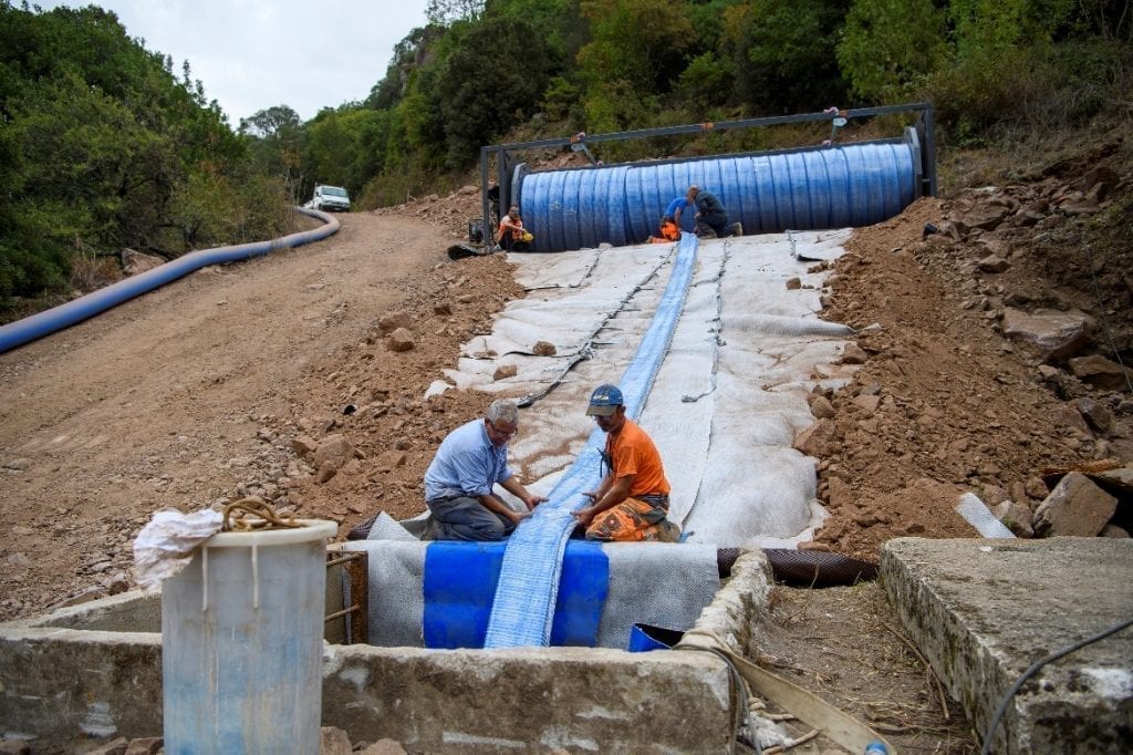
The trenchless technology chosen for the project by the principal is known as ‘hose lining’. The method employs flexible, reinforced multiple-layer hose with unique characteristics. It features an intermediate reinforcing layer entirely made of Kevlar®, a synthetic aramid fibre able to withstand high operating pressure, guaranteed over time, and special parts called couplings, specifically researched to anchor the hose to the ends of the pipe sections.
The reinforced hose is self-supporting, meaning that it is able to wholly absorb the internal pressure of the conveyed fluid without adhering to the pipe and leaving an annular gap. The three different layers forming the hose are schematically illustrated in Figure 4.
During the installation process and regardless of the type of fluid conveyed, the outer sheath that protects the inner, load-bearing core in Kevlar® is made of abrasion-resistant polyethylene (PE). The central core is formed by a seamless layer of Kevlar®. As well as absorbing the entire operating pressure, the aramid fabric absorbs the tensile force when the reinforced hose is inserted. The inner layer used when drinking water is conveyed is in polyethylene PE, suitable for contact with drinking water as specified by Ministerial Decree DM 174 of 2004. Since the reinforced hose is flexible, thousands of metres can be wound on reel frames for compact transport, while pull-in-place lining of the old pipe by hydraulic winch is facilitated even through curved pipe sections.
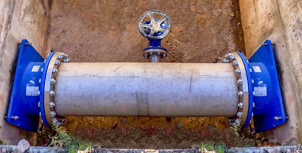
The second part of ‘hose lining technology’ comprises special, specifically designed end pieces. The couplings used when medium pressures are involved are formed by a profiled inner core and an outer sleeve housing a deformable metallic retaining ring. When the coupling is installed, two-component resin injected through a valve on the outer sleeve forces the metallic ring and, consequently, the tube, into the inner core. The connection will be permanent after the resin has been cured for at least 12 hours at 20°C, during which it acquires high tensile strength. Each end of the couplings has a standard flange used for re-connection to the pipeline or for housing a special piece. In addition, this system enables customised solutions to be provided for special applications. As in the case of Bosa, where each coupling had to be inserted into existing traps and plugs were used for anchoring to their sides.
Hose liner installation
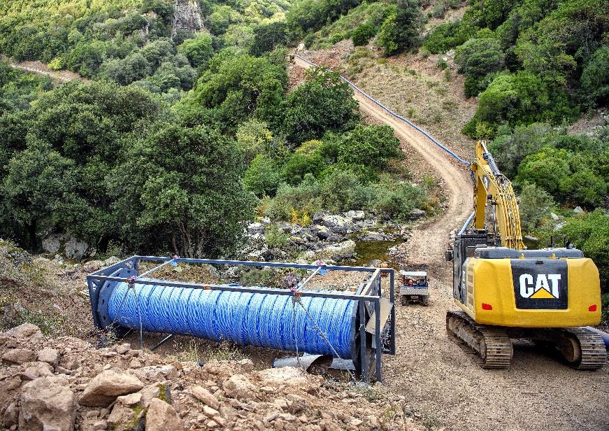
To ensure the least possible impact on the pipeline and surrounding vegetation, we proceeded by working directly and solely on pipe sections in existing pits after their covering slabs had been removed. To reach these pits we created access tracks by widening the existing paths.
Once we were able to reach the work sites, the installation stages were carefully organised to optimise the resulting work level to the maximum and reduce, as far as possible, the time the pipeline had to remain disconnected:
- bypass preparation
- sectioning of pipeline in pit
- preliminary video inspection operations
- liner insertion and assembly of couplings
- installation of special parts
- testing and re-commissioning
- emptying and removal of bypass.
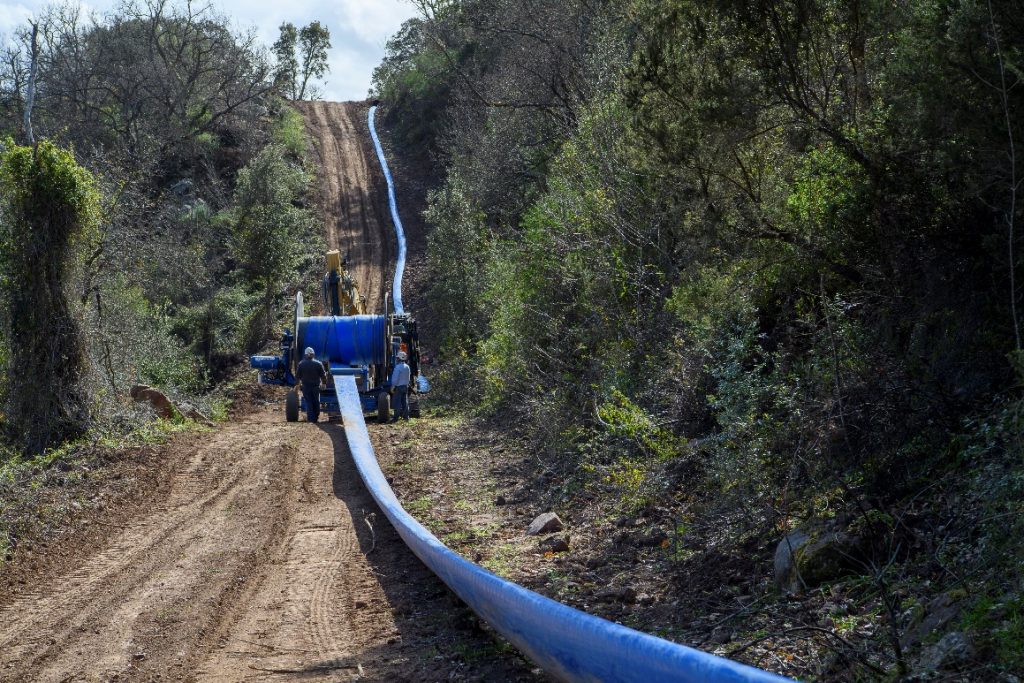
Thanks to the particular and efficient method we employed to prepare the bypass, we were able to terminate the hose liner installation process in a triple succession of the steps described above.
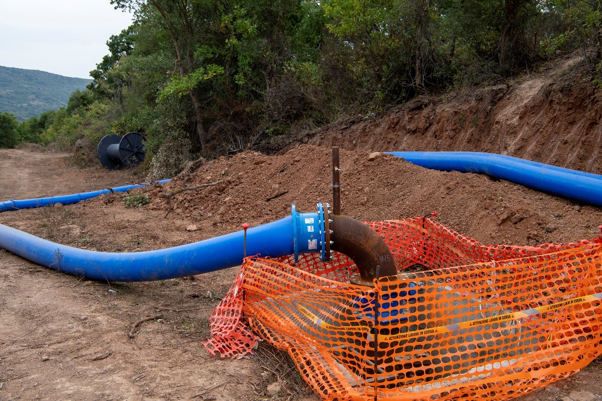
The bypass was obtained by using a reinforced hose as self-supporting liner and by making the most of its flexibility to overcome the difficult logistical conditions in which the work had to be performed.

